33+ pressure transducer block diagram
Method of signal generation 17 Given a basic block diagram of a. Test for Strength The best method to prevent power shock would.
2
A schematic diagram of the transducer Gems Sensors Series 200016 bar absolute is shown in Figure 6.

. In the considered model the so called dead time of the transducer resulting from the delayed response to the input signal was. A block diagram approach is proposed to analyze the dynamic characteristics of a thickness-mode piezoelectric transducer at its resonance frequency. This section will describe the configuration of the circuit design and its particular application for pressure measurement.
Search result of Pressure transducer block diagram Search By Products. The DP215 is a differential water pressure transducer. Pressure transducer block diagram.
The block diagram of passive transducer is shown in below figure. The input-output function of. Or 0 to 10V dc.
Transducers are classified into the following different types. The model of transducer in block form is presented in Fig. In this effect when electricity is applied to a piezoelectric material it undergoes physical.
Fig-2 shows the block diagram of the circuit. 4 to 20 mA The robust. 16 EXPLAIN how a strain gauge pressure transducer produces an output signal including.
Pressure Detector Circuits and Block Diagram Basics Within the block circuit diagram illustrated below the sensing element senses the pressure of the monitored system and converts the. Handheld Pressure Calibrator with. 481 Block Diagram and Interface Definition.
16 Pics about Instrumentation Loop Diagrams Instrumentation Tools. Instrumentation Loop Diagrams Instrumentation Tools. The ultrasonic piezoelectric transducer works on the principle of the converse piezoelectric effect.
A Pressure Transmitter is a two-part device consisting of a sensing transducer and a circuit that transmits a standard instrumentation electrical signal representing a physical. Transducers are named as level. 3 Wire Pressure Transducer Wiring Diagram Source.
Method of detection b. 33 Pressure Transducer Wiring Diagram - Wiring Diagram. As shown in the figure passive transducer will produce variation in the passive element in accordance with the variation in the.
Variations in water pressure deflect the measurement diaphragm which in turn bends. 1 to 5V dc. Block Diagram of a Sensor Transducer Assembly.
AKS 32 and AKS 33 are pressure transmitters that measure a pressure and convert the measured value to a standard signal.

Pressure Gauge Water Traps And Pigtail Siphons Pressure Gauge Siphon Water Traps

Calameo 1983 Alfa Romeo 33 Workshop Manual

Calibration Procedure Of Differential Pressure Transmitter By Using Hart Transmitter Control Systems Engineering Digital Pressure Gauge
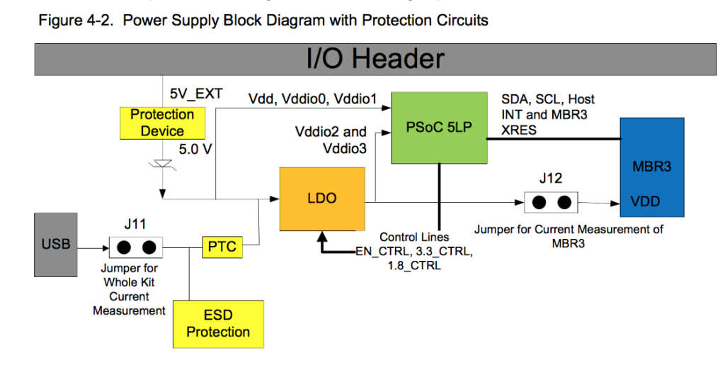
Psoc Creator Iot Expert

Hitachi Zx870 5b 870lc 5b 870h 5b 870lch 5b 870r 5b Hydraulic Excavator Electrical Circuit Diagram 2 By Heydownloads Issuu
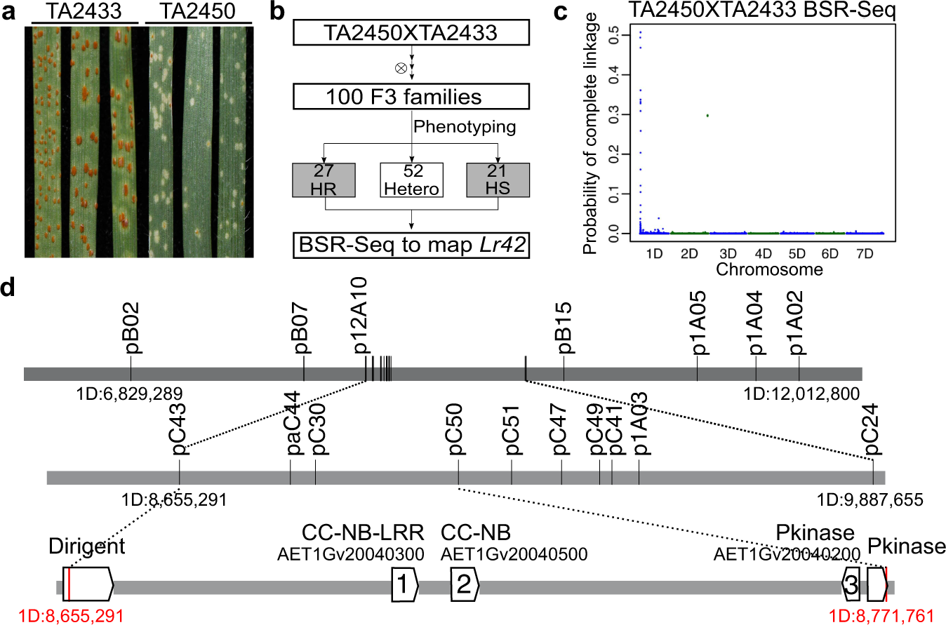
Cloning Of The Broadly Effective Wheat Leaf Rust Resistance Gene Lr42 Transferred From Aegilops Tauschii Nature Communications

Force Pressure Switch Circuit Using Fsr Gadgetronicx Force And Pressure Circuit Circuit Diagram
2
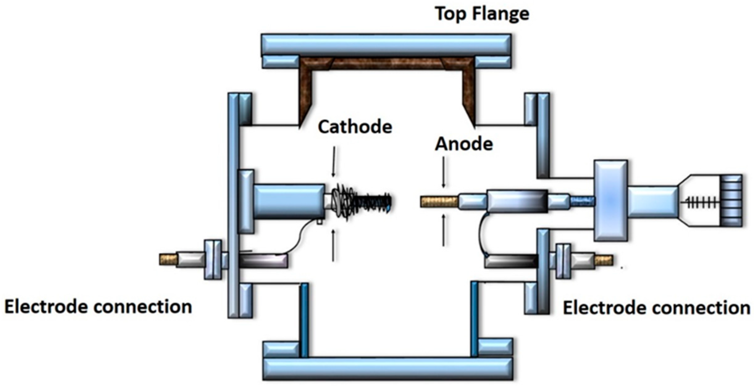
C Free Full Text An Overview Of The Recent Progress In The Synthesis And Applications Of Carbon Nanotubes Html

Signaling Recognition Events With Fluorescent Sensors And Switches Chemical Reviews
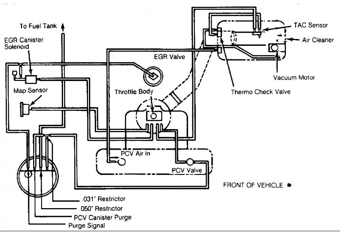
Renix Vacuum Diagrams For The Engine Bay Jeep Cherokee Forum

Hitachi Zx870 5b 870lc 5b 870h 5b 870lch 5b 870r 5b Hydraulic Excavator Electrical Circuit Diagram By Heydownloads Issuu

Smart Pressure Transmitter Configuration Transmitter How To Apply Electronics Components

Low Cost Platform For Multiplexed Electrochemical Melting Curve Analysis Acs Measurement Science Au
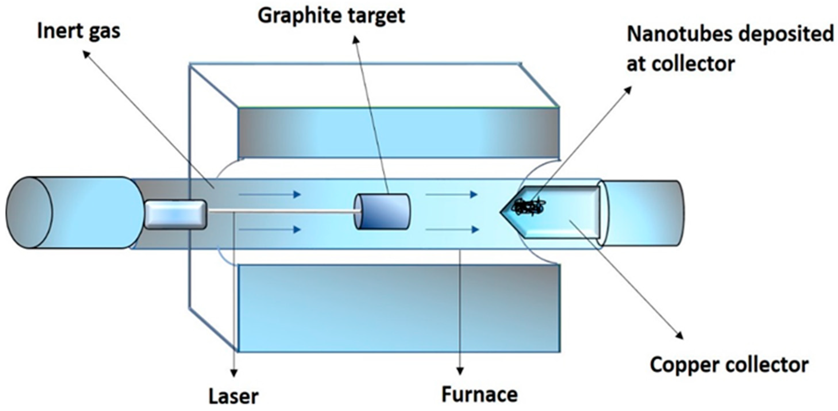
C Free Full Text An Overview Of The Recent Progress In The Synthesis And Applications Of Carbon Nanotubes Html

Tire Pressure Monitoring System Tpms Tire Pressure Monitoring System Pressure Circuit Diagram

Pressure Sensor Guide Sensor Wheatstone Bridge Pressure